STM32回顾性学习,只记要点
1 Keil设置
- Configuration(帮叟)
- Editor->Encoding->Encode in UTF-8 without signature 支持中文
- Editor->C/C++ Files->Tab size->4 更改缩进为4
- Color & Fonts-> C/C++ Editor files-> Text -> Font->14 调整字体大小
- Text Completion -> Symbols after 3 Characters 选中 自动补全设置(需重启软件)
- Options for Target(魔术棒)
- C/C++-> Include Paths 声明所有包含头文件的文件夹
- C/C++-> Define内定义USE_STDPERIPH_DRIVER 使用标准外设编译,这是使用库函数的条件编译
- Debug 下拉列表选择对应调试器
- Debug 调试器旁边Settings Flash Download里勾选Reset and Run
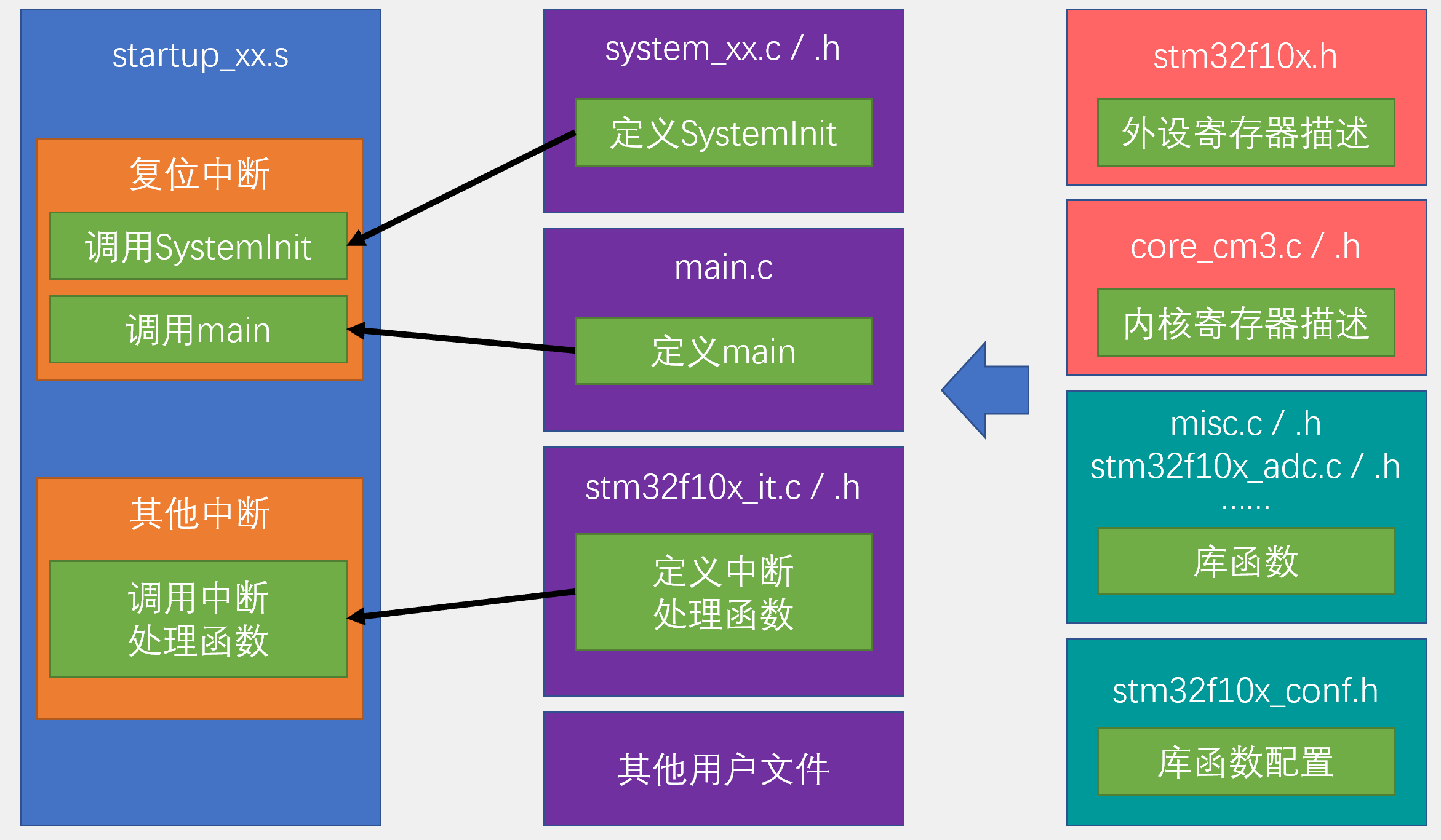
2 STM32内部电路结构
3 STM32编程
### 3.1 方式: 1. 直接调用寄存器(需查阅STM32文档) 2. 库函数 3. HAL
### 3.2 库函数
3.2.1 GPIO配置
1
2
3
4
5
6
7
8
9
10
11
12
13
14
15
16
17
18
19
20
21
22
#include "stm32f10x.h"                  // Device header

int main(void)
{
	//使用库函数将位于GPIOC的Pin13对应的LED点亮(0亮1灭)
	//1. 打开clk使能
	RCC_APB2PeriphClockCmd(RCC_APB2Periph_GPIOC, ENABLE); 	//打开GPIOC的clk使能
	//2. 定义GPIO结构体
	GPIO_InitTypeDef GPIO_InitStrcture;					//定义一个名为GPIO_InitStrcture的结构体,并在下面描述结构体的内容
	GPIO_InitStrcture.GPIO_Mode = GPIO_Mode_Out_PP; 	//通用推挽输出
	GPIO_InitStrcture.GPIO_Pin = GPIO_Pin_13; 			//将控制目标定为Pin13(跳转:点击Class为member的GPIO_Pin)
	GPIO_InitStrcture.GPIO_Speed = GPIO_Speed_50MHz;	//将Pin13速度定位50MHz
	//3. 初始化GPIO
	GPIO_Init(GPIOC, &GPIO_InitStrcture); 				//初始化GPIOC
	//4. GPIO设置为高/低电平
	GPIO_SetBits(GPIOC, GPIO_Pin_13);
//	GPIO_ResetBits(GPIOC, GPIO_Pin_13);
	while (1)
	{

	}
}
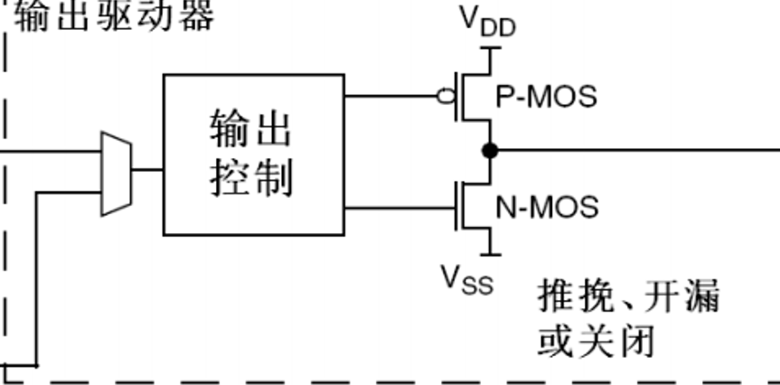
3.2.2 寄存器输出模式
1](https://cdn.jsdelivr.net/gh/skycity11/picture@master/pic/2c7f31407fb659852c99794bdb36cf6a109a5301a0faf34c0028e22e1b30f4b3.png)
- 推挽
- P-MOS/N-MOS都导通。高电平:1,低电平:0
- 开漏
- P-MOS关闭,N-MOS导通。高电平:高阻(浮空),低电平:0
- 可外接5V上拉电阻,将高电平输出为5V
- 关闭
- P-MOS/N-MOS都关闭。电平由外部电路控制45
```
—————————————————————————————————————
Ongoing
—————————————————————————————————————